FPV Drones
Complete 6S 5-Inch FPV Freestyle Build Guide: Parts, Assembly, and Setup
A step-by-step walkthrough of building a reliable 6S 5-inch FPV freestyle quadcopter with the DJI O3 system, from frame assembly through Betaflight configuration.
Introduction
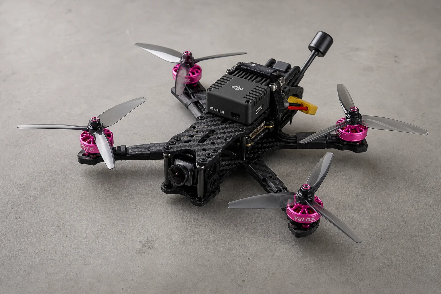
Building a 6S 5-inch FPV freestyle quadcopter can feel overwhelming when you first encounter the sheer number of components and technical terms involved. This guide walks you through the entire process step by step, from frame assembly to Betaflight configuration, so that even if you are completely new to FPV, you will have a clear path forward.
This is not an ultra-budget build where you are just hoping everything works. Instead, it prioritizes reliability and durability, making it an excellent choice if you are getting into digital FPV. The components are proven performers that can handle the demands of freestyle flying, including crashes and hard landings.
Component Selection
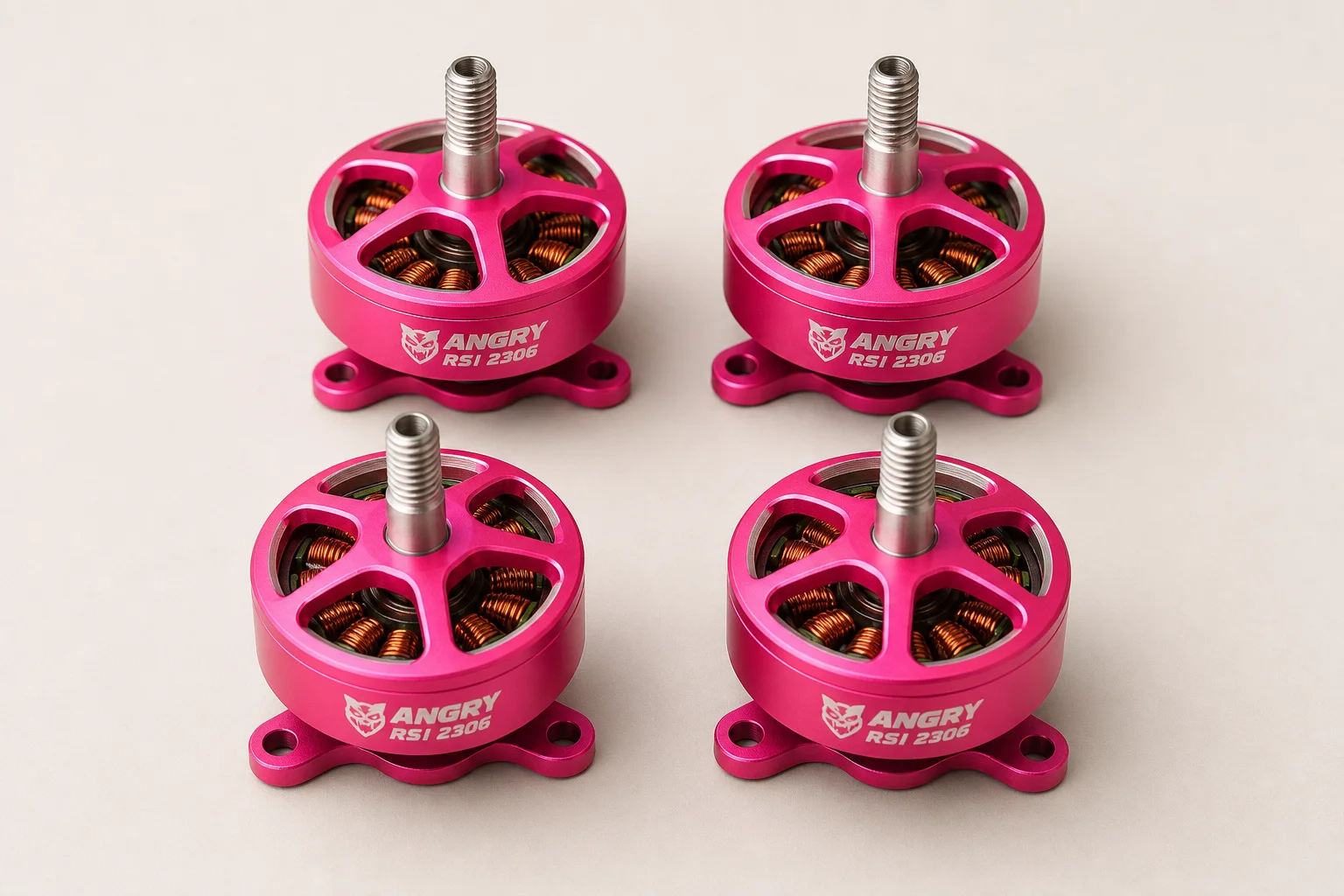
Motors: Meepskin 2207 Neon
The Meepskin 2207 Neon motors are a solid choice for freestyle flying. These 250 KV motors come in eye-catching neon pink, along with neon yellow and other KV options. At their current sale price of around 11 dollars each, they offer excellent value without compromising performance. Meepskin also offers a 10 percent discount coupon code for additional savings.
Electronic Speed Controller and Flight Controller Stack
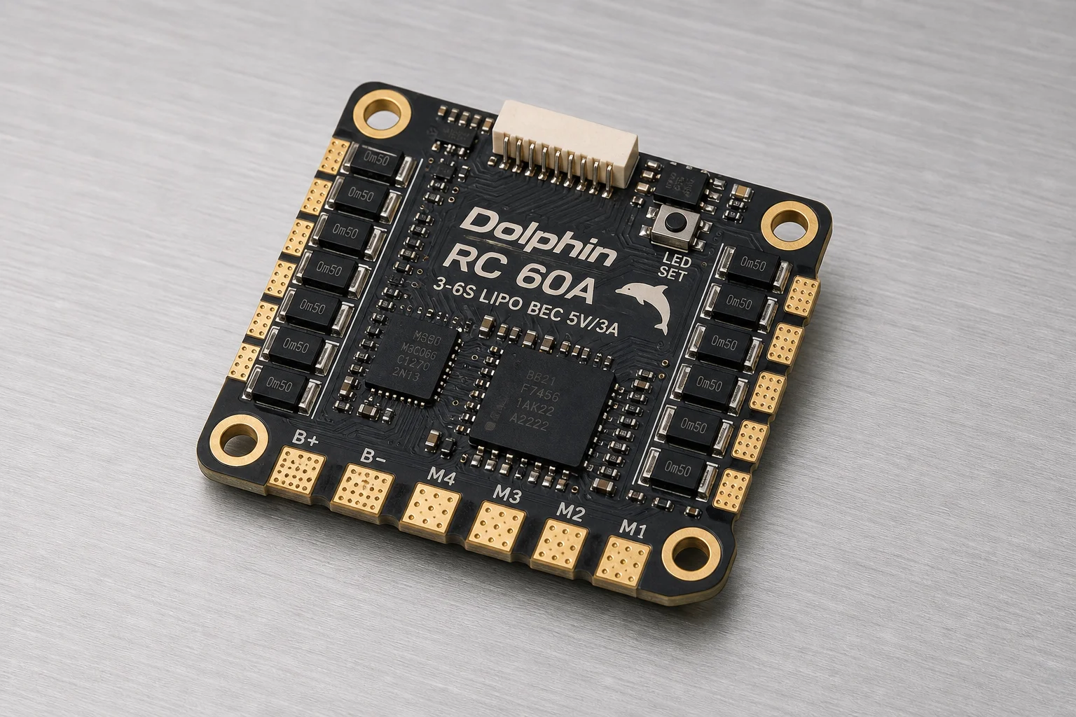
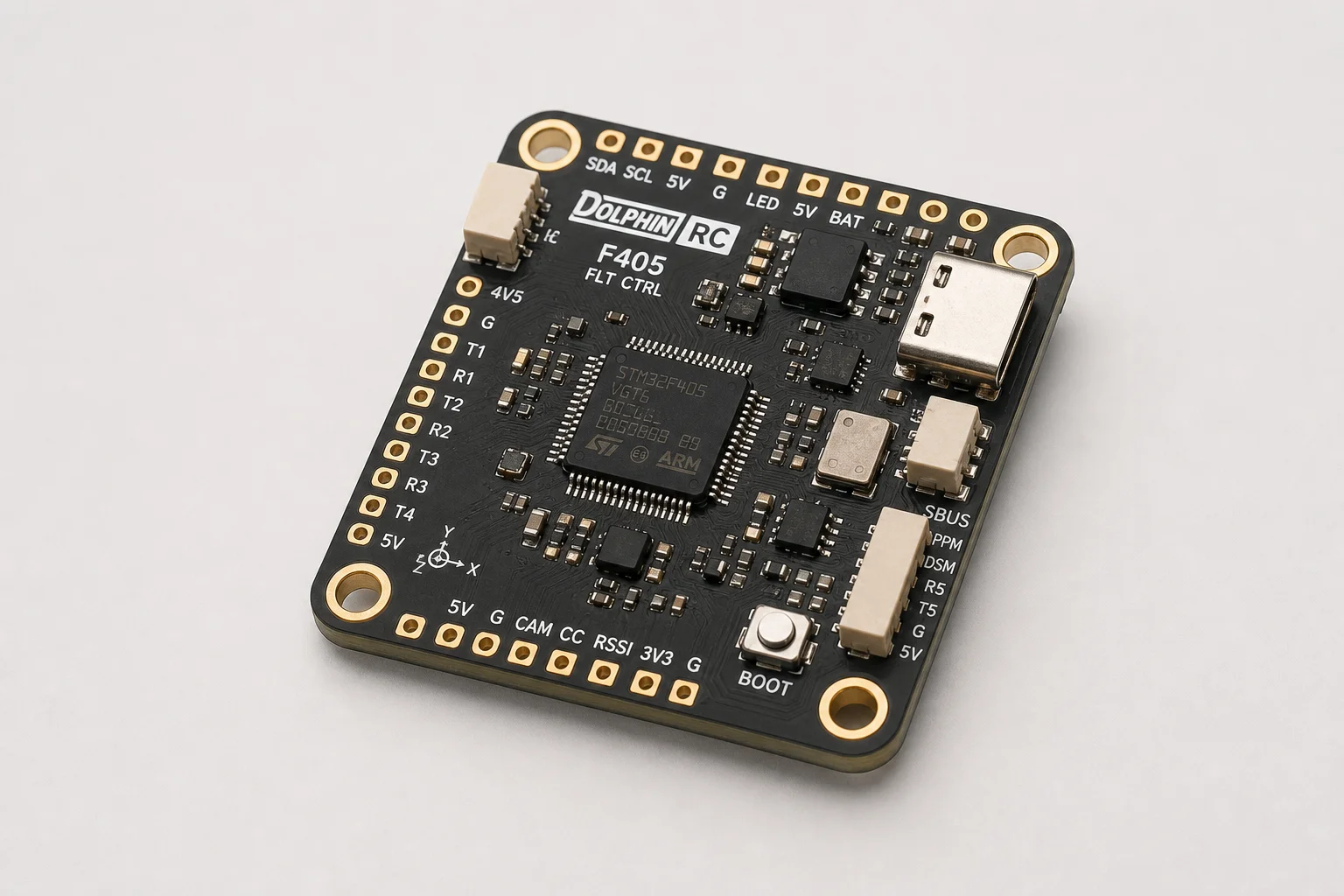
The Dolphin RC stack combines a 60-amp ESC with an F405 flight controller, selling for approximately 60 dollars. The F405 is generally considered superior to the older F411, making this a particularly good value. The stack includes six UART ports, one soft serial TX, a 16-megabyte blackbox, and AM32 ESC firmware support, which is rapidly becoming an industry standard.
The kit also includes a medium-sized capacitor, silicon dampers, and pre-soldered connectors for various connections, reducing assembly complexity.
Frame: Mark 5X
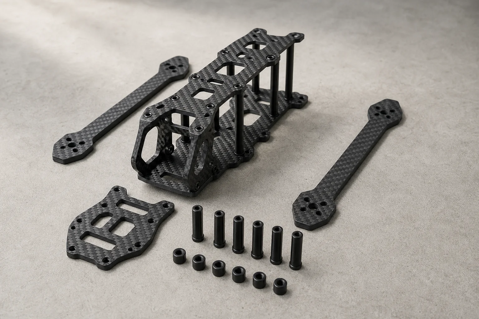
The Mark 5X frame is a budget-friendly option available on AliExpress for around 20 dollars. While it is a clone of the original GAP RC design rather than the official version, it performs excellently for freestyle builds. The frame is designed to accommodate the DJI O3 air unit and includes provisions for 3D-printed TPU parts, which you can either order pre-installed or add yourself.
Video Transmitter: DJI O3 Air Unit
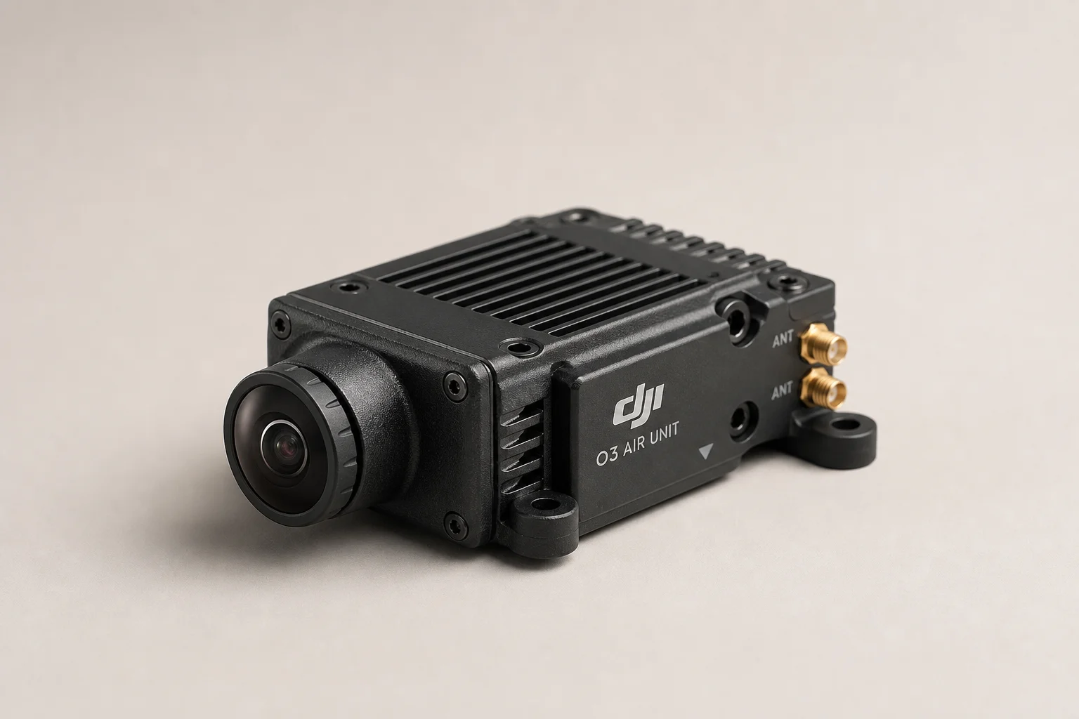
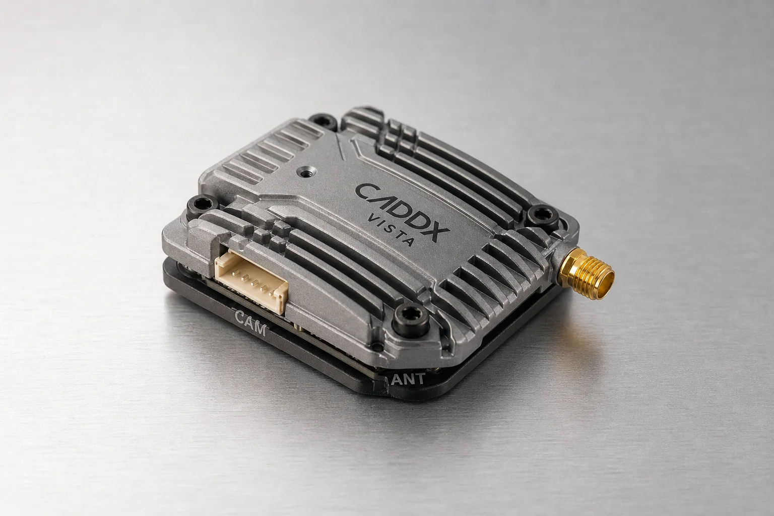
The DJI O3 delivers the best digital FPV experience available, though it is becoming harder to find new and is not budget-friendly. If cost is a concern, the Caddx Vista is a solid alternative available for around 60 dollars used. The build process remains largely the same regardless of which digital VTX you choose.
Receiver: Solo Good ExpressLRS
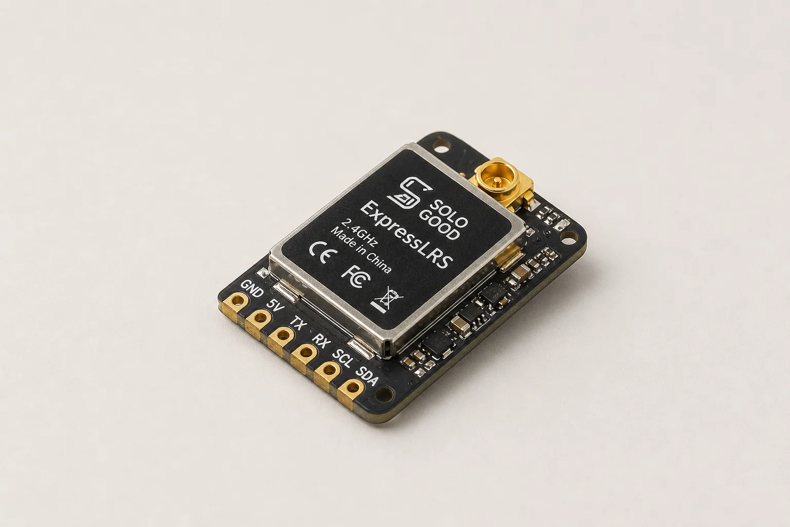
The Solo Good 2.4 GHz ExpressLRS receiver is one of the most affordable options available and is more than sufficient for freestyle flying, which does not require long-range capability. ExpressLRS is gaining traction as a reliable, open-source control link standard.
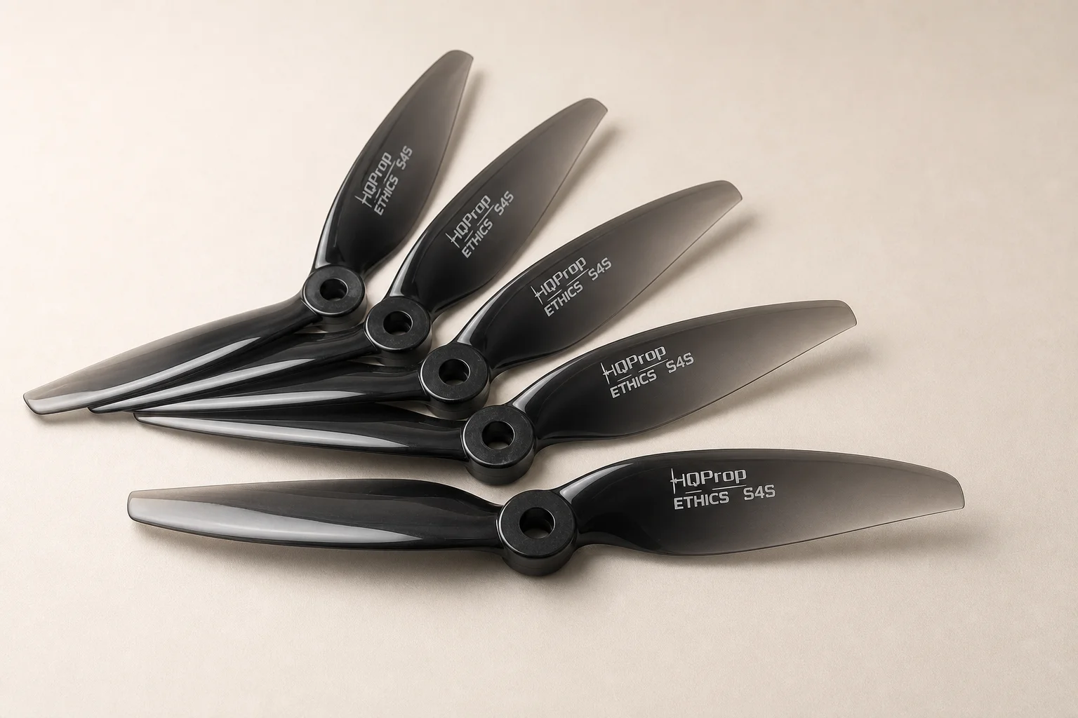
Propellers: HQ Prop Ethics S4S
The HQ Prop Ethics S4S propellers are the final component in this build. These props are designed to work well with the motor and ESC combination selected.
Tools and Materials You’ll Need
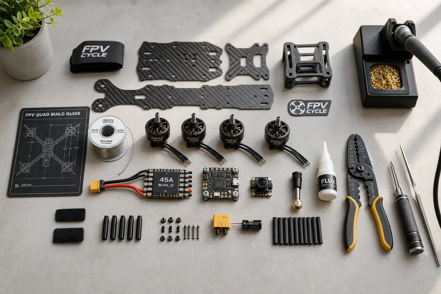
Before starting assembly, gather the following tools and materials:
- A large, clean workspace with plenty of room to spread components
- Hex driver set for frame assembly
- Electric screwdriver (optional but helpful)
- 8 mm nut driver for propeller installation
- Craft knife for small tasks
- Precision side cutters
- Wire stripper
- Quality flux and solder
- Soldering iron with multiple tip sizes (larger tip for XT60 connectors, smaller tip for receiver)
- Cloth tape for motor wires
- Zip ties
- 320-grit sandpaper for smoothing carbon edges
- Thread locker for screws
- Smoke stopper (highly recommended for protecting against shorts)
The smoke stopper is particularly valuable. It plugs between your battery and quad and acts like a fuse, cutting power if a short or other fault is detected before expensive components are damaged.
Frame Assembly and Preparation
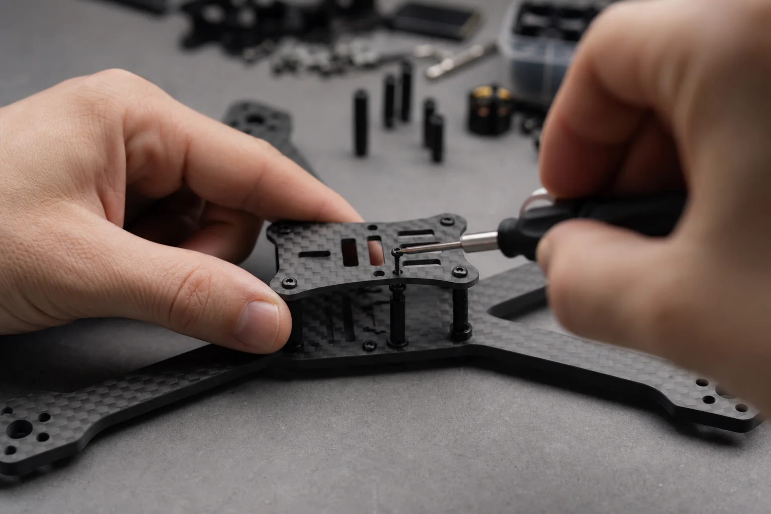
Start by sanding the carbon fiber edges with 320-grit sandpaper to remove sharp burrs and prevent carbon splinters from getting into your fingers during assembly.
Lay out all frame parts on your workspace before beginning. This gives you a clear picture of what you are working with and helps the assembly process flow more smoothly.
Begin by securing the carbon X plate to both base plates using the center screw. Then slide the arms in from the sides and secure them. Note that front and back arms are not identical; look for the small notch that distinguishes them.
Since budget frame kits typically do not come with thread locker pre-applied, add a small amount to the bolts to prevent them from loosening during flight. Do not overdo it; a little goes a long way.
Install the standoffs in the back section of the frame where the video transmitter will sit. Use the longer M3 screws for standoffs and the shorter ones for base plate threads. Periodically tighten screws by hand to ensure proper torque without over-tightening.
Mount the camera cage using short M3 screws in front and longer ones in back. The aluminum side plates have an inside and outside face, so orient them correctly.
Connect the two aluminum side plates with the small spacer, tightening one screw on each side. Install the screws for the stack (ESC and flight controller), adding thread locker to the nylon lock nuts. Finally, mount the top plate. If using the included anti-slip pad, do not punch out all the holes; this gives the battery more surface area to grip during flight.
Soldering the Motor Wires and Power Distribution
Before soldering, remove everything from the frame that does not need to be soldered, keeping your workspace clean and organized.
Mount the motors with TPU motor protectors if you plan to fly in tight spaces or perform aggressive freestyle maneuvers. These protectors provide extra cushioning during crashes.
Insert silicon grommets into the ESC mounting points. This takes practice but becomes easy once you understand the technique.
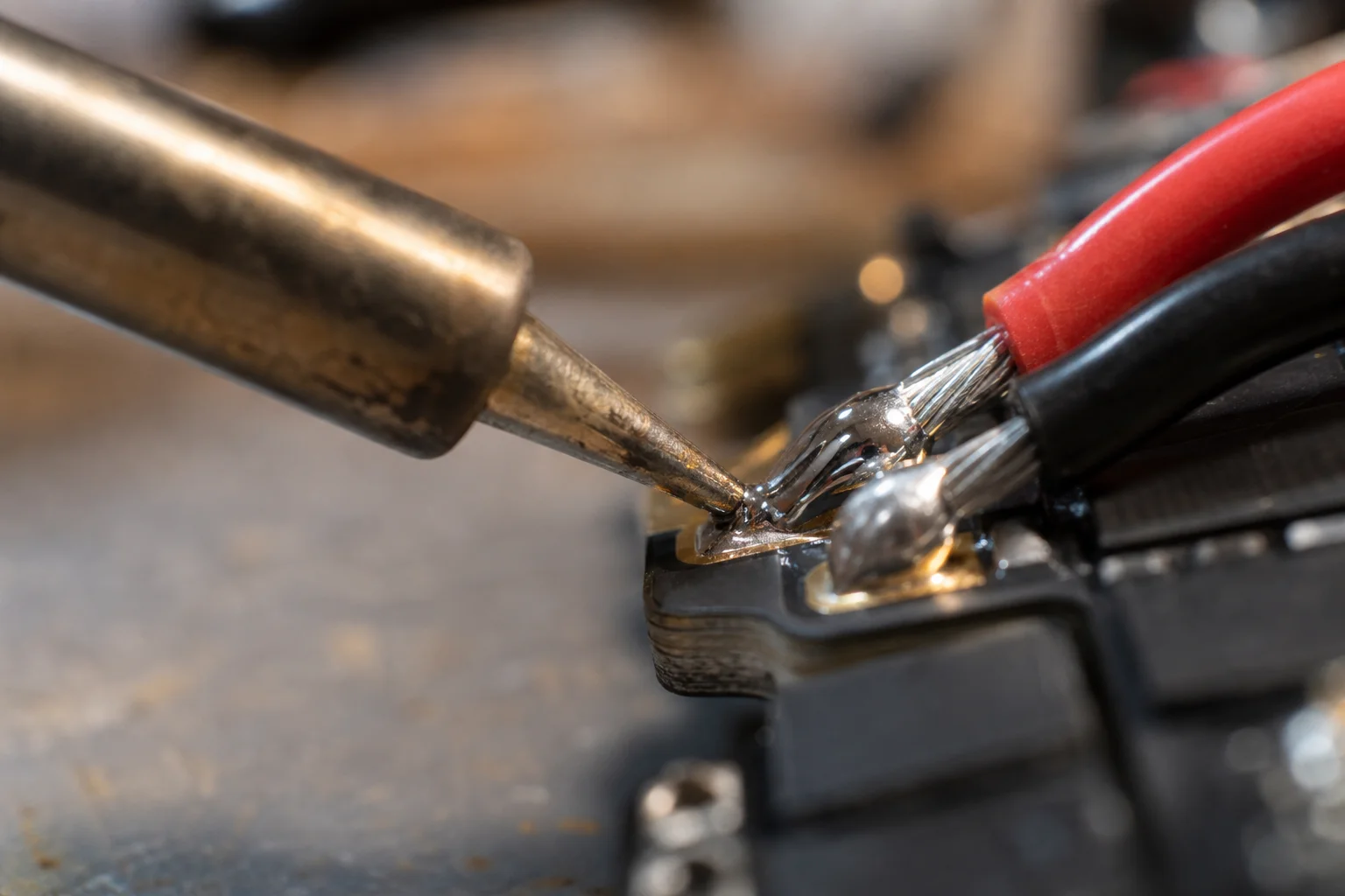
Follow this soldering order: motors first, then the XT60 connector, and finally smaller components like the VTX and flight controller. By the time you reach the XT60, the ESC is already warmed up, making it easier to achieve solid joints.
When cutting motor wires, leave them slightly longer than you think you need; you can always trim them later. When stripping wires, expose just enough to cover the entire ESC pad for a solid connection. Twist the wire strands together to keep everything neat and avoid stray wires.
Tape off the ESC before soldering to prevent solder micro-droplets from landing on sensitive areas and causing shorts when the battery is connected.
Soldering has a steep learning curve, but once you understand that you need plenty of heat, results improve quickly. Aim for functional joints rather than perfection. If it holds, that is a win. Do not stress about making your soldering look perfect; focus on reliability.
For the XT60 connector, prep the pads with flux, heat them, and tin them before soldering the wires directly onto the pads. Use plenty of heat and ensure the solder flows and bonds with the pad; a weak joint can break under stress during flight.
After soldering is complete, clean the board with isopropyl alcohol to remove flux residue.
Test the build using a smoke stopper before connecting the main battery. If everything is correct, the smoke stopper remains on, you see no magic smoke, and the ESC plays its startup tone through the motors.
Installing the Flight Controller and Receiver
Solder the ExpressLRS receiver to the flight controller. Hold the receiver in place using a soldering jig or tape to prevent it from sliding around. Connect power to power, ground to ground, RX on the receiver to TX on the flight controller, and vice versa.
Mount the flight controller using silicon grommets to reduce vibrations. Ensure the arrow on the FC points forward to set the correct gyro orientation.
Installing the Video Transmitter and Camera
The DJI O3 comes mostly pre-assembled. Plug in the connector but remove the Sbus wire from the connector if you plan to use both Elus and Sbus on the same UART in Betaflight. You can either pull the pin out of the plug or cut the wire; removing it cleanly allows you to reuse it later if needed.
Unplug the UFL antennas from the air unit, thread them through the TPU mount, and reconnect them. Handle UFL connectors carefully; pulling too hard or at the wrong angle can rip the socket off the board.
Press the DJI O3 antenna mount onto the standoffs so it sits snugly. Route the ExpressLRS receiver antenna through the TPU mount and secure the receiver using heat shrink tubing.
Connect the O3 air unit to the flight controller using the cable you modified by removing the Sbus wire. Press the air unit into the TPU holder and tuck the O3 camera cable between the FC and ESC.
Mount the camera using two screws on each side through the silicon dampers. Start with a moderate camera tilt angle rather than an aggressive angle; you can adjust it later to match your flying style.
Completing the Build
Secure the flight controller using lock nuts, tightening them just enough to hold the FC firmly without over-tightening. The silicon dampers still need room to absorb vibrations.
Install the top plate, propellers, and battery straps. Always use two battery straps on a 5-inch quad; one strap is insufficient and your battery will fly out on crashes.
Run the motor wires between the FC and ESC to prevent battery straps from pressing directly against them. Constant friction from the straps can wear through wire insulation over time.
Tape down the motor wires last, routing them neatly along the frame arms.
Betaflight Configuration and First Flight
Before connecting to Betaflight, enter the password in the web interface of your ExpressLRS receiver so your radio can communicate with the quad.
In Betaflight, go to the Ports tab and set the correct UART for your receiver, then enable serial RX.
Go to the Presets tab, search for DJI O3, select the appropriate preset, specify which UART it is on, and apply it.
Set up ExpressLRS in Betaflight by going to Presets, searching for ExpressLRS, and selecting the preset that matches your radio’s packet rate (250 Hz or 500 Hz). Check the boxes for serial receiver and HD Freestyle.
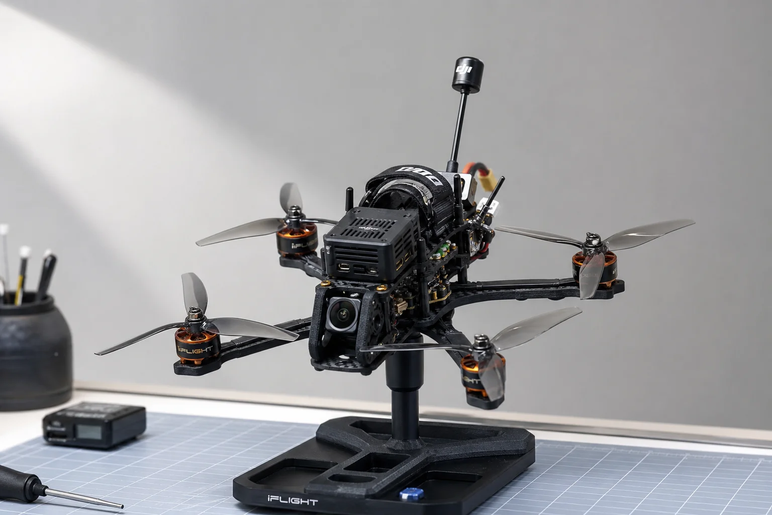
Go to the Motors tab and verify motor direction without props installed. Use the motor direction wizard to ensure actual spin direction matches the diagram. Do not enable the reversed option unless you know what you are doing.
If your ESC supports DShot (as the Dolphin RC ESC does), set it to DShot 300. This enables the RPM filter under the P tab, which improves flight smoothness.
Set up flight modes, including arming, beeper, and crash flip. Crash flip is particularly valuable for recovering from inverted crashes.
Keep stock PIDs for your first flights. They are usually fine, especially with a well-built quad. You can adjust and tweak settings as you gain experience.
Cost and Performance
This build can be completed for around 150 dollars if you use a budget analog VTX and apply available coupon codes. For someone starting with an analog CSX kit, this represents an affordable upgrade path into a full 5-inch freestyle rig without breaking the bank.
In testing, this build performs surprisingly well at its price point. The motors deliver strong punch and acceleration comparable to more expensive alternatives. The Dolphin RC stack shows no dropouts or unusual behavior during tuning and simply works reliably.
The real measure of success for a freestyle build is durability. These components are designed to survive crashes, hard landings, and aggressive flying. If they prove as durable as more expensive alternatives while costing significantly less, this represents a genuinely good option for budget-conscious builders.
Conclusion
Building a 6S 5-inch FPV freestyle quadcopter is achievable for anyone willing to take their time with assembly and soldering. This guide provides a complete roadmap from component selection through first flight. Start with quality tools, follow the steps carefully, and do not hesitate to practice soldering on scrap boards before working on your actual build. The FPV community is welcoming to beginners, and with patience and practice, you will have a reliable, durable freestyle quad ready for years of flying.
Further reading
Related Reviews
FPV Drones
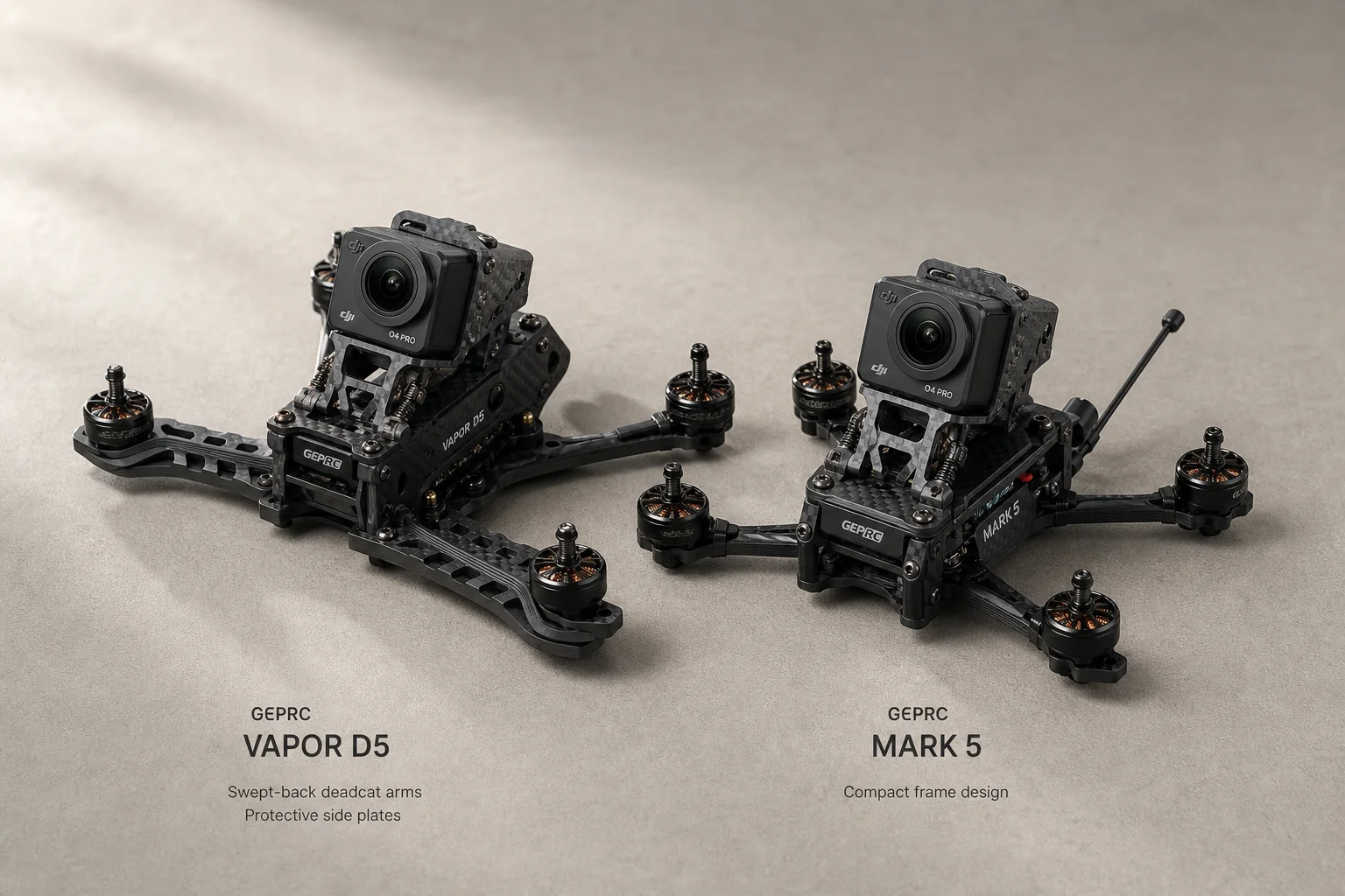
Best 5-Inch FPV Drones 2026: Vapor D5 vs Mark 5 Comparison and Review
A detailed comparison of the GEPRC Vapor D5 and Mark 5 5-inch FPV drones, covering performance, durability, price, and which suits different flying styles.
FPV Drones
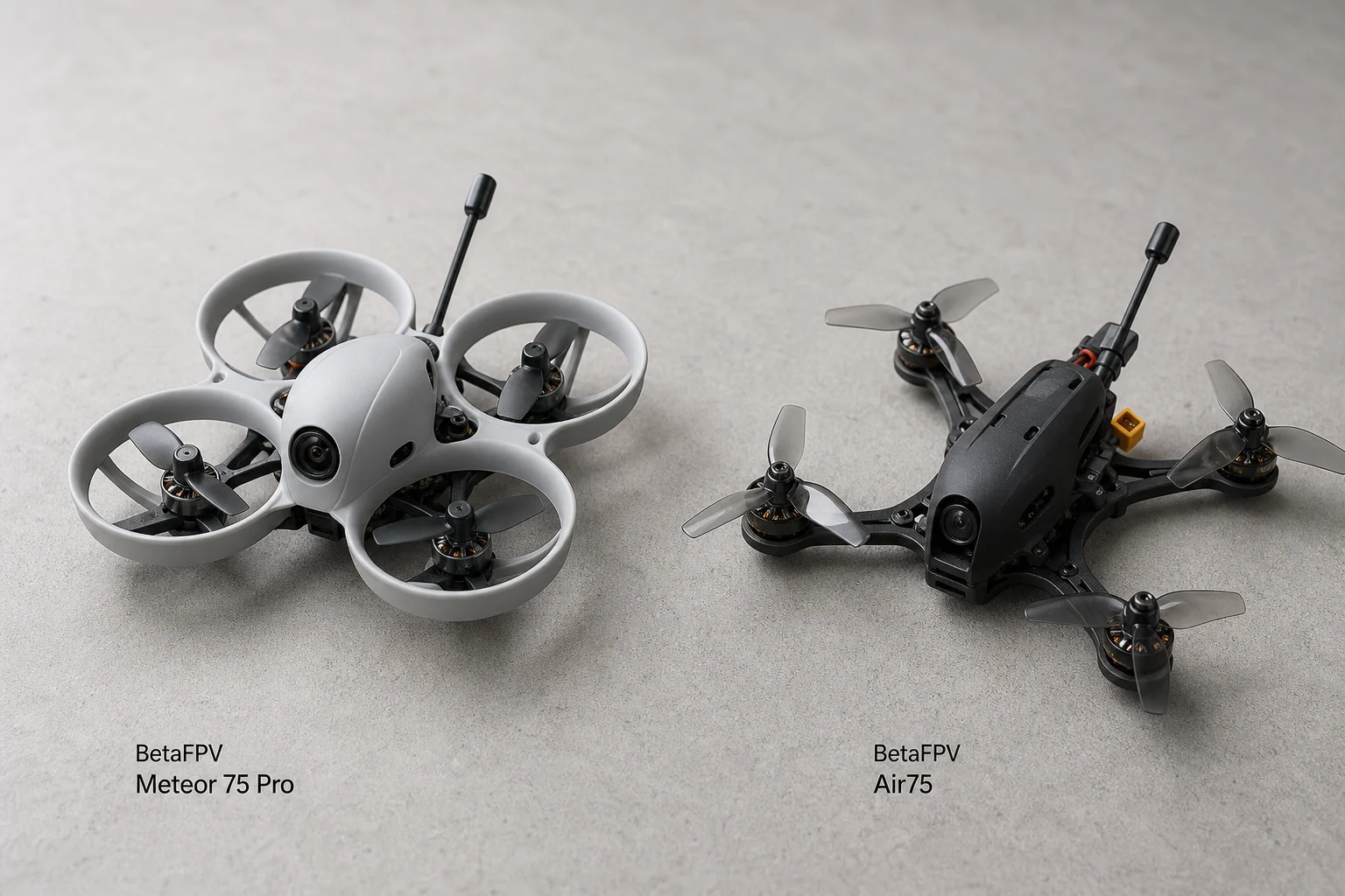
BetaFPV Meteor 75 Pro vs Air75: Which Tiny Whoop Suits Beginners Better
A practical comparison of two popular 75mm FPV drones, tested by a beginner pilot to help you choose between durability and handling.
FPV Drones
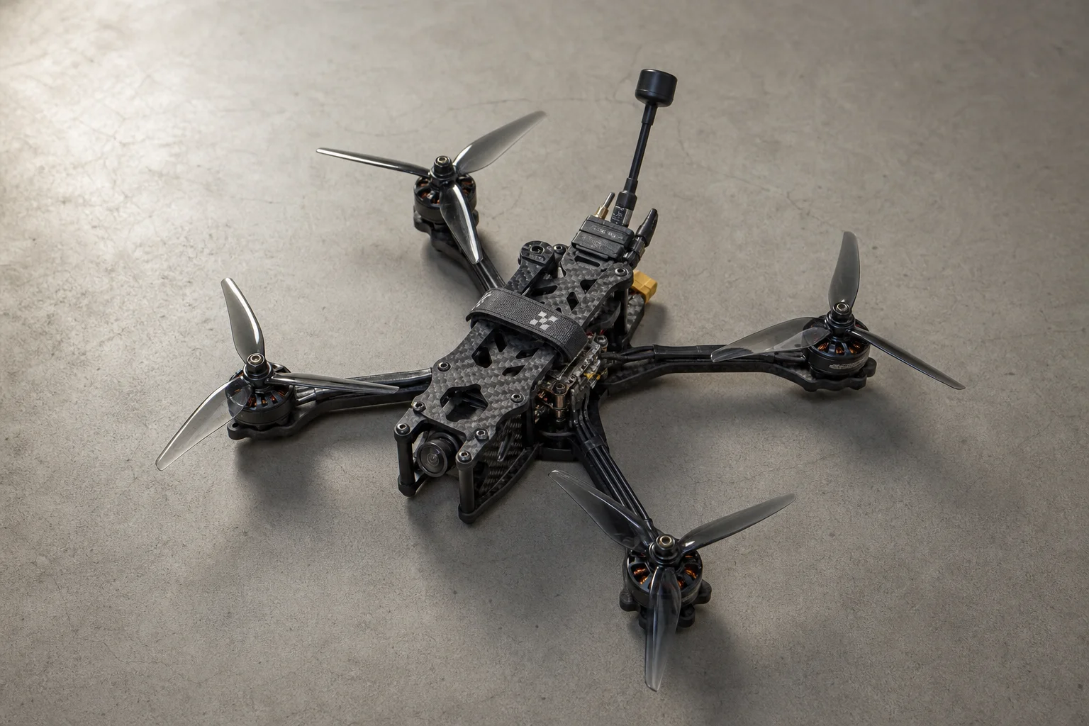
How to Build a 7-Inch FPV Drone: Complete Assembly Guide
A practical walkthrough for assembling an affordable 7-inch long-range FPV quad, from frame to flight controller, with all components and soldering techniques explained.