FPV Drones
How to Build a 7-Inch FPV Drone: Complete Assembly Guide
A practical walkthrough for assembling an affordable 7-inch long-range FPV quad, from frame to flight controller, with all components and soldering techniques explained.
Introduction
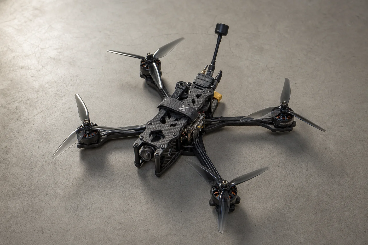
Building a 7-inch FPV drone from individual components is achievable for anyone willing to follow a methodical assembly process. A 7-inch quad offers a practical balance between flight time and ease of control compared to smaller 5-inch models, and can carry a camera for extended flights. This guide walks through the complete assembly, from frame preparation through final electrical checks, covering all the components and soldering techniques you’ll need to succeed.
Understanding Drone Anatomy
Every FPV drone consists of several core systems working together. The frame holds all electronics and is typically made from carbon fiber, which is lightweight, reliable, and affordable. For hobby flying and practice, a budget frame copy performs adequately; premium frames primarily benefit racing or professional freestyle pilots by reducing vibrations and improving control feel.
The flight controller (FC) is the drone’s brain, calculating position and sending commands to the electronic speed controllers (ESCs) to spin the motors. Most modern flight controllers ship integrated with the ESC as a single stack, simplifying the build. The motors convert electrical power into mechanical thrust, while the video transmitter (VTX) broadcasts the camera feed to your goggles. A receiver handles control signals from your transmitter, and the camera provides the FPV video feed.
Understanding how these systems interconnect helps you troubleshoot issues and make informed component choices during assembly.
Choosing Your Components
Frame: GepRC Mark 4
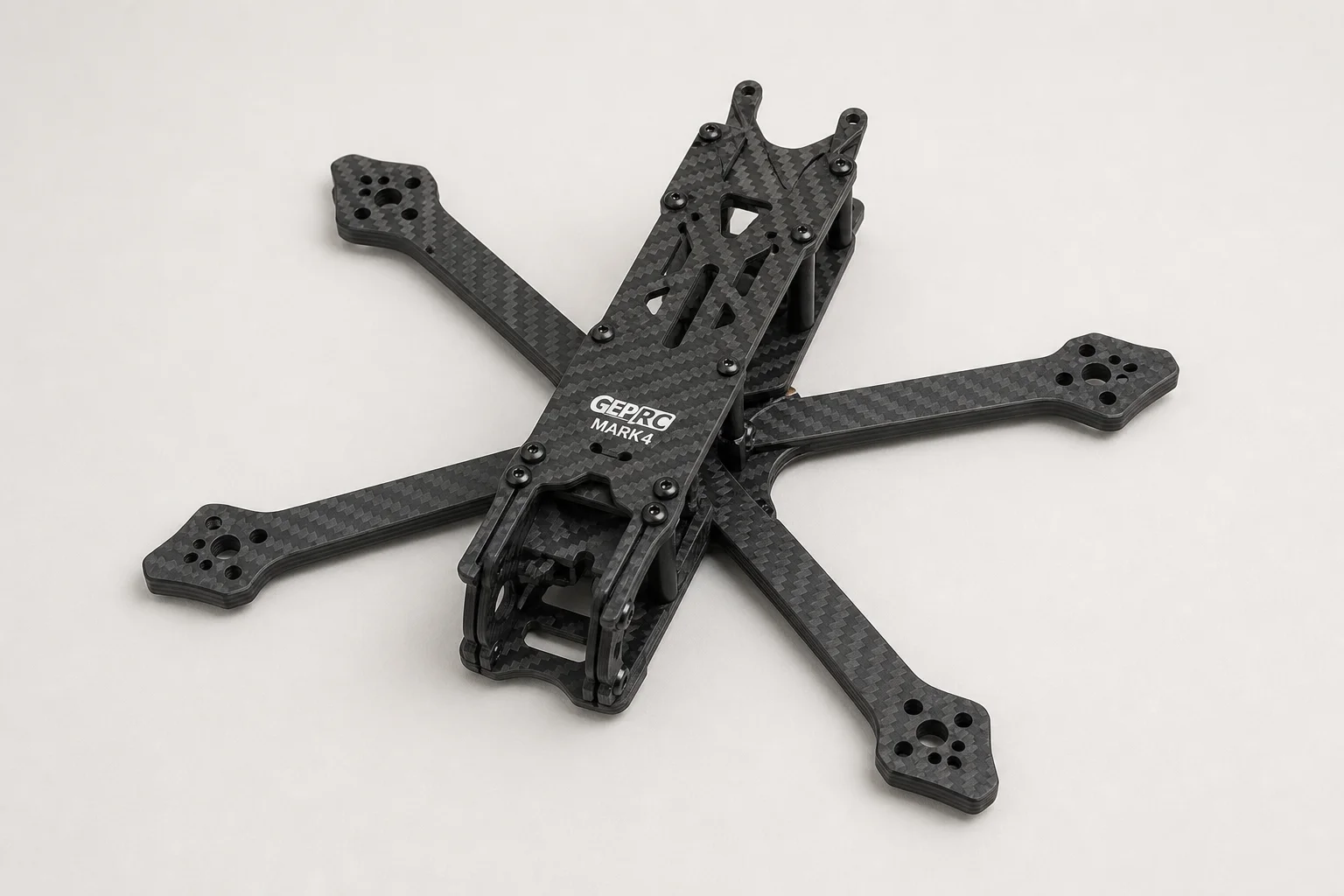
The frame is the structural foundation. A cheap copy of the GepRC Mark 4 offers good balance between price and build quality for hobby flying. Verify that your chosen frame has standard mounting holes compatible with your flight controller stack and that it accommodates your camera’s mounting pattern (typically 19x19mm holes).
Flight Controller and ESC: SoloGood F405
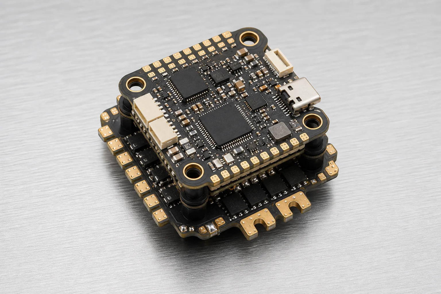
The SoloGood F405 combines a flight controller with a 55A integrated ESC. Key specifications to verify: standard mounting holes for your frame, battery voltage range (this stack supports 3S to 6S), and maximum current per motor. With a 55A ESC, your total battery output should not exceed 220A. A Li-Ion battery limited to 80A works safely with this stack.
Motors
Budget motors perform surprisingly well despite costing three to four times less than premium brands like Black Hornet, Mamba Toka, or XING. Pair them with quality propellers such as HQProps 7040 to maximize efficiency and flight performance.
Camera: Caddex Ratel 2
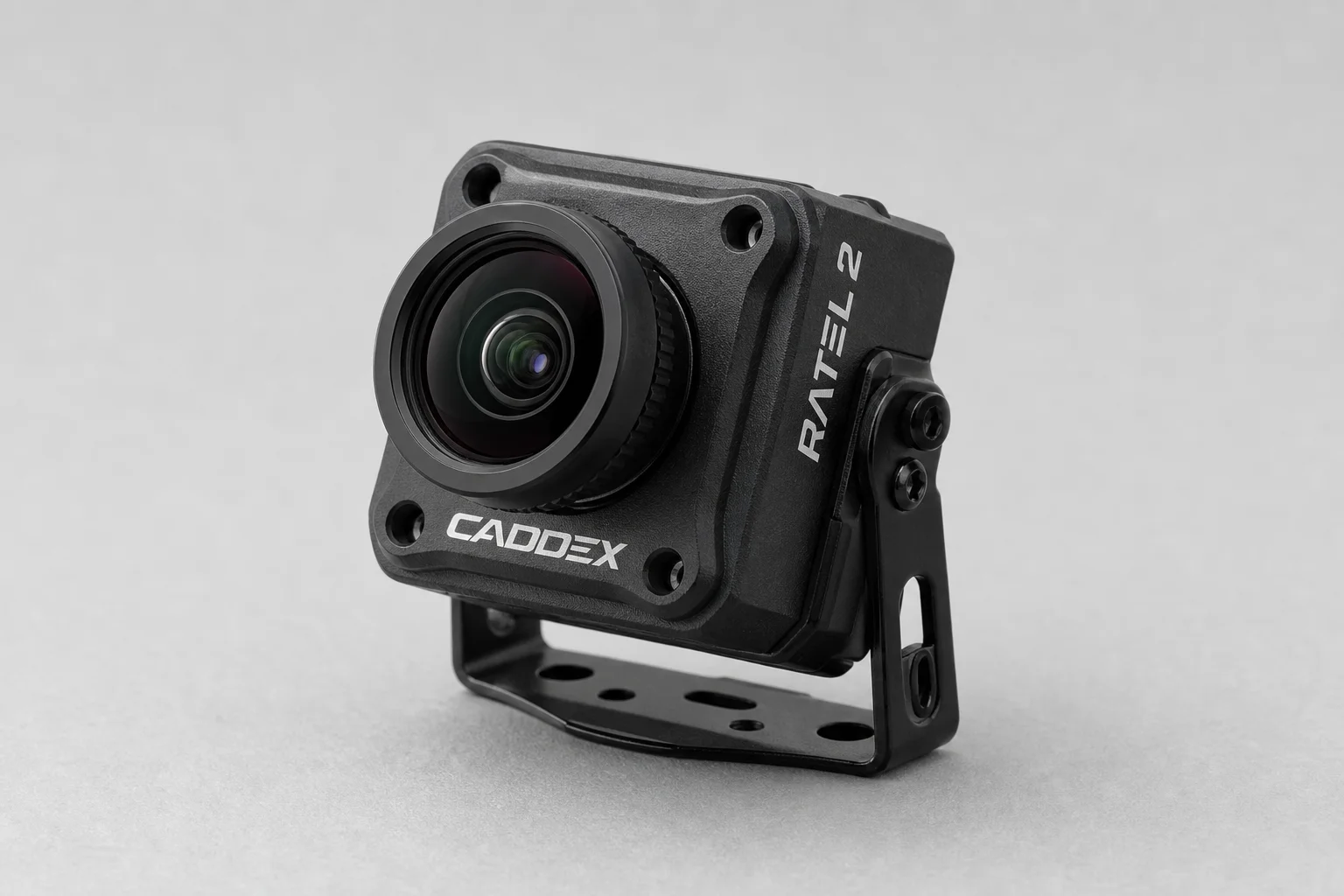
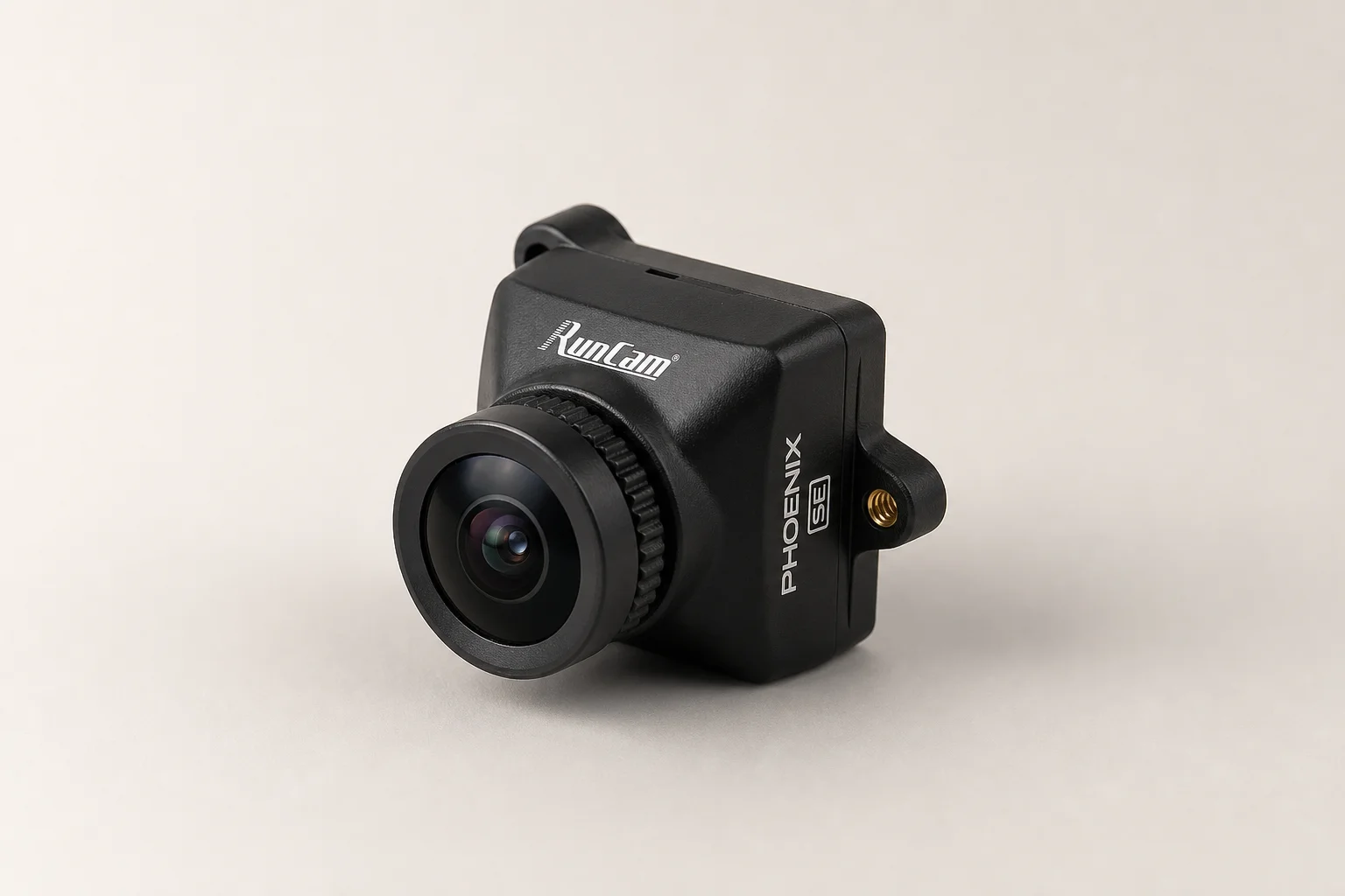
For analog FPV systems, the Caddex Ratel 2 delivers better image quality than many competitors. The Runcam Phoenix SE is a close alternative worth comparing. Ensure your chosen camera has 19x19mm mounting holes to fit the Mark 4 frame without requiring adapters.
Video Transmitter: Rush Tank Max Solo
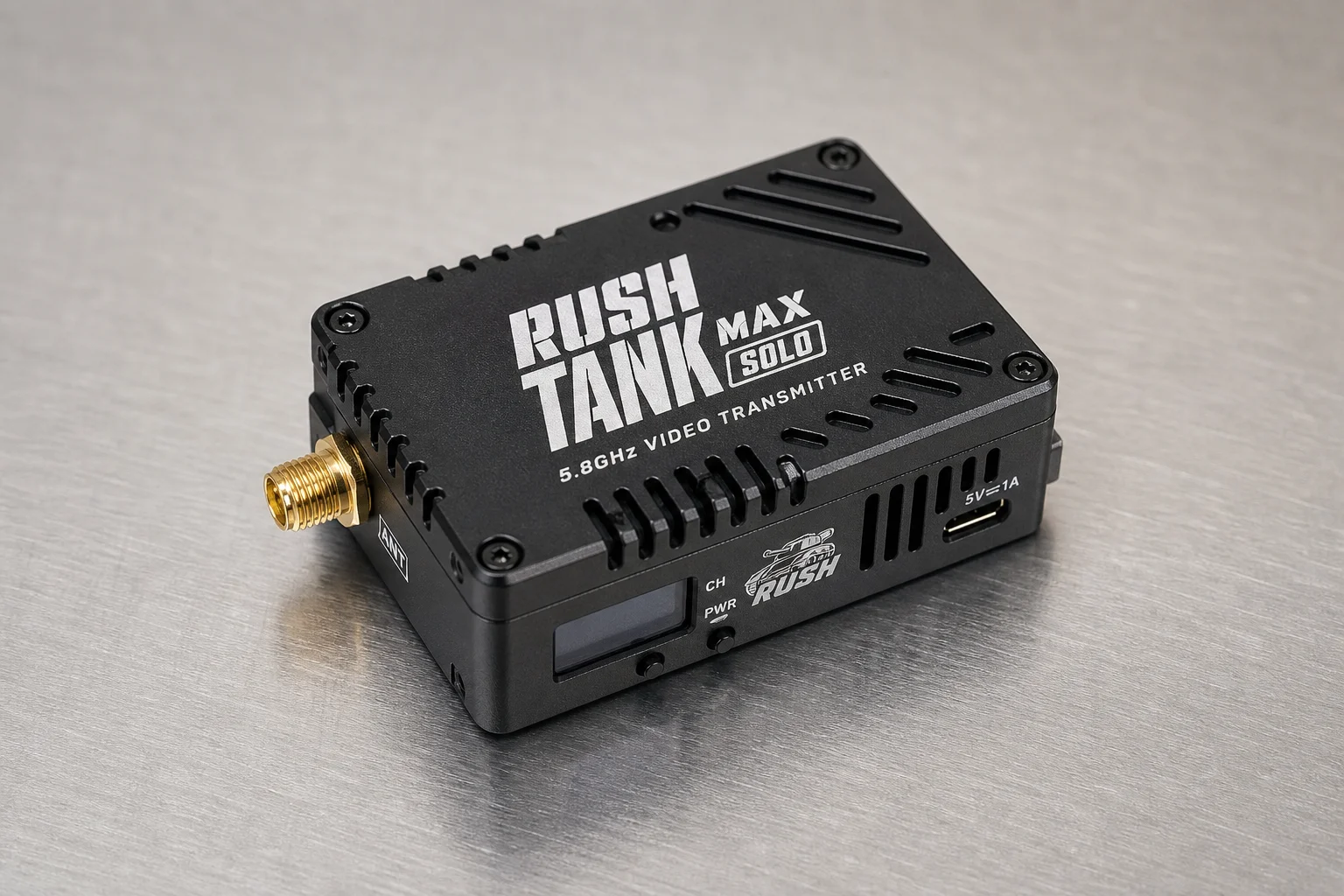
A quality VTX is critical for long-range flights. The Rush Tank Max Solo provides 2.5W of power, essential for maintaining signal over distance. It includes internal cooling for summer flying and a convenient storage box for small screws. Verify that your VTX supports the battery voltage your setup uses.
Antenna: Rush Cherry
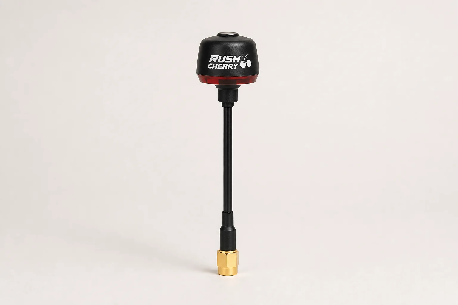
The Rush Cherry antenna, especially the second-generation version, provides reliable signal transmission. Choose the longer variant to avoid signal gaps and interference. Right-hand polarization is recommended for analog video systems. Position the antenna so it stays above the battery during flight for optimal signal strength.
Receiver
An ELRS receiver offers an open-source platform with lower cost and customization options. The 915 MHz frequency is superior for long-distance flights compared to the standard 2.4 GHz, provided your transmitter supports this frequency and protocol.
Assembling the Frame
Start by unpacking all frame components. The largest piece is the bottom plate. Locate the two smaller front and back sections and the smallest screws. Insert screws into the smallest holes and secure them with long standoffs, ensuring screw heads sit flush in the recesses.
Attach the two arms using short standoffs and the cover piece. Insert long screws from the bottom, then place arms and cover on top. Secure with standoffs first, then tighten screws into nuts. Repeat on the other side. Finally, insert the longest screws into the center holes (some frames may not have threads here, which is normal).
Set aside remaining frame parts for later use. Do not fully tighten any screws yet; you’ll adjust everything after mounting electronics.
Soldering the ESC
Soldering is the most technically demanding part of the build. Solder power wires diagonally to maximize space for the capacitor and video transmitter. Use a 2mm hex screwdriver to position wires directly on the frame if needed to get the angle right.
Soldering the ESC
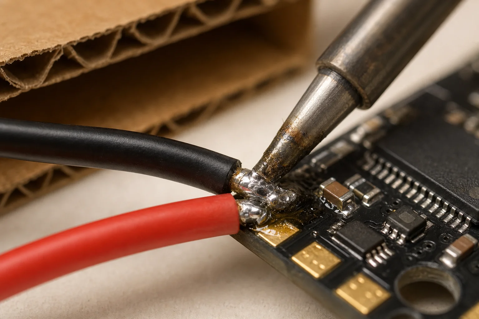
On the ESC, the black wire connects to the minus pad and the red wire to the plus pad. Tin the black wire first, then tin the ground pad. Protect your fingers with cardboard from the parts box. Set your soldering iron to 380°C with a large tip, apply flux, and solder the wire. Ensure solder melts on both the pad and wire simultaneously. Repeat for the positive contact, which requires less heat.
Once power wires are soldered, solder the capacitor. Use a larger capacitor with the same specifications as the included one, cutting legs to 10-15mm length. Polarity is critical: the minus symbol on the capacitor body must solder to the minus pad. Add a small amount of solder to hold the capacitor in place, then melt everything together for a solid joint.
Tin all remaining pads and clean the board with isopropyl alcohol. Before mounting the ESC to the frame, connect the plug and vibration dampers, and add nuts to secure it in place.
Wiring the Motors
Unpack each motor and screw it onto a frame arm using a 2.5mm hex screwdriver. Ensure screws do not touch the motor windings, which could cause a short circuit; if they do, replace them with shorter M3 screws. Route motor wires along the arm and secure them in the middle with a zip tie.
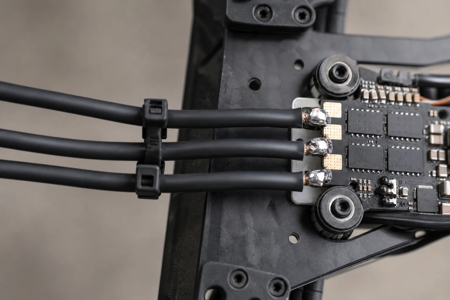
Solder the three motor wires to the first three ESC pads in any order. Position wires one above another outside the ESC to avoid blocking ventilation and to allow motor replacement without full disassembly. Cut and tin each wire, add flux, and solder to the pad. Use the same soldering tip as for the ESC but reduce temperature to 350°C for motors. Repeat for all motors, then add one more zip tie to each arm and clean the ESC with isopropyl alcohol.
Installing the Flight Controller
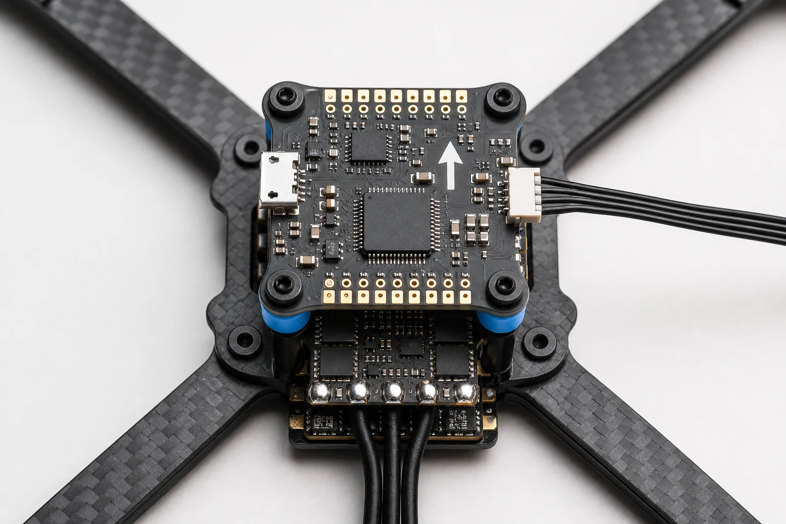
Add vibration dampers to the flight controller, then connect it to the ESC using the socket labeled S1 to S4. Add nuts but do not overtighten; a small gap between FC and ESC reduces vibrations and improves flight performance. The arrow on the FC must point toward the drone’s front (opposite the capacitor side).
Mount 3D-printed antenna mounts if desired (many designs are freely available online). The Mark 4 has a hole for the video antenna; the receiver antenna can be zip-tied to an arm.
Connecting the Video Transmitter
Remove the sticker from the VTX and connect the plug. You’ll see a 5V out pin and GND pin meant for powering the camera; since you’ll connect the camera directly to the flight controller, remove these wires by cutting or carefully extracting them from the connector.
Arrange remaining wires neatly. Apply double-sided tape to create a small gap between the VTX and the carbon frame, reducing electrical noise. The tape also secures the VTX in place. Connect the pigtail from the VTX box to the 3D-printed mount without sharp bends, then connect it to the VTX (you should hear a click). Place the VTX in position and secure with a zip tie.
The VTX has four wires: black (ground), red (DC IN, minimum 9 volts), yellow (video signal, connects to VTX pad on FC), and a data pin (connects to any UART, such as TX4). Use a smaller soldering tip and reduce temperature to 300°C. Cut wires to length, tin them, and solder in place.
Connecting the Receiver
Carefully unpack the receiver and remove the antenna if pre-connected. The receiver has four pins. Use black for ground and red for 5V consistently. For signal wires, use white for RX and yellow for TX (or your preferred color scheme, but remember the pinout). Tin the receiver pads, solder all wires, and clean with isopropyl alcohol.
Organize and secure the wires, then reconnect the antenna. Cover the receiver with transparent heat shrink tubing so you can see the status LED if needed. Mount the antenna to the drone using a 3D-printed mount or by attaching it to an arm, ensuring it is not bent and propellers will not strike it.
Soldering to the Flight Controller
Connect the receiver wires to the flight controller: black to GND, red to 4.5V, white (RX from receiver) to TX on the FC, and yellow (TX from receiver) to RX on the FC.
Connect the camera plug and use a 1.5mm hex screwdriver to secure the camera mount to the frame. Ensure the connector faces upward (correct orientation); if upside down, the image will be flipped. Leave screws slightly loose for now. Trim camera wires to appropriate length and solder: black to GND, red to 5V, and yellow (signal) to the CAM pad. Clean the flight controller thoroughly with isopropyl alcohol to remove flux residue.
Final Assembly Checks
Before closing the top cover, perform several electrical checks. First, screw on the video antenna; powering the VTX without an antenna can damage it.
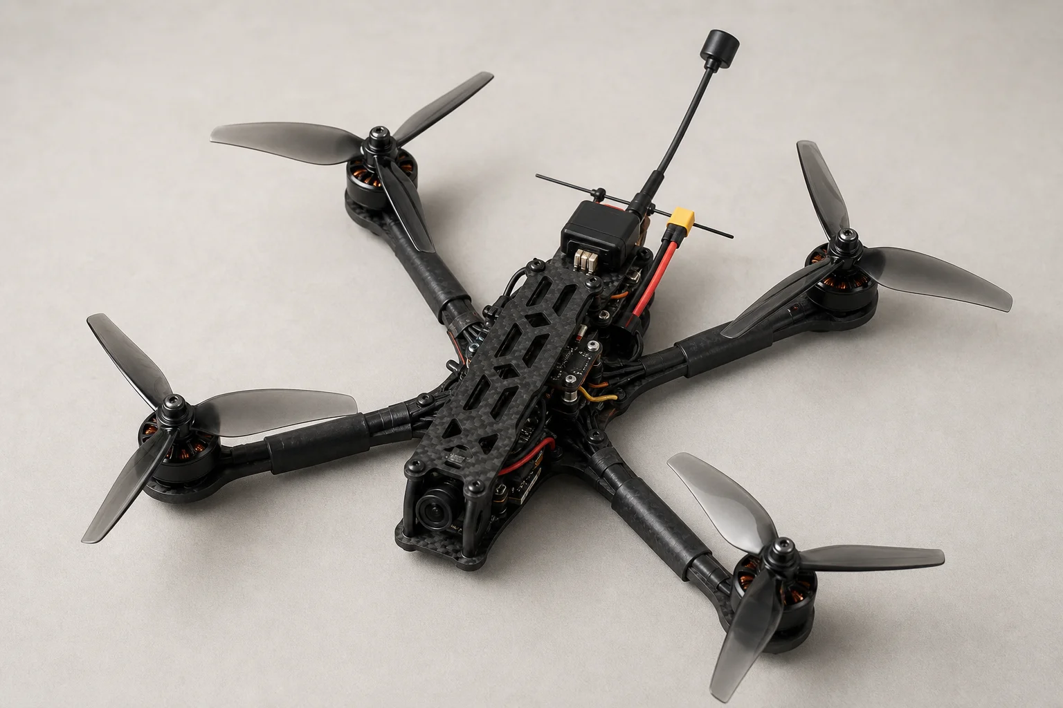
Run a continuity test using a multimeter between the positive and negative power pads. A brief beep (one to two seconds) is normal as the multimeter charges the capacitor. A continuous beep indicates a short circuit; inspect the board visually and unplug components one by one to isolate the issue.
Test the motors by placing one multimeter probe on a ground pad and the other on each motor output pad. There should be no continuity. It is normal for the three pads of a single motor group to show continuity between each other (they are internally connected), but different motor groups should not show continuity.
Before connecting the battery, strongly consider purchasing a smoke stopper, a small safety device that cuts power if a short circuit occurs. It costs only a few dollars but can prevent expensive electronics damage and avoid the risk of a LiPo battery fire.
Once you connect the battery, you should hear startup tones. If you do, you have successfully assembled your quad. Install the top cover and tighten all screws to eliminate unwanted vibrations. Your drone is now ready for firmware upload and configuration before its first flight.
Conclusion
Building a 7-inch FPV drone requires patience and attention to detail, but the process is straightforward when you follow each step methodically. The components listed here provide a solid foundation for long-range, stable flying. With assembly complete, the next phase involves uploading firmware, configuring the flight controller, and preparing for your first flight.
Further reading
Related Reviews
FPV Drones
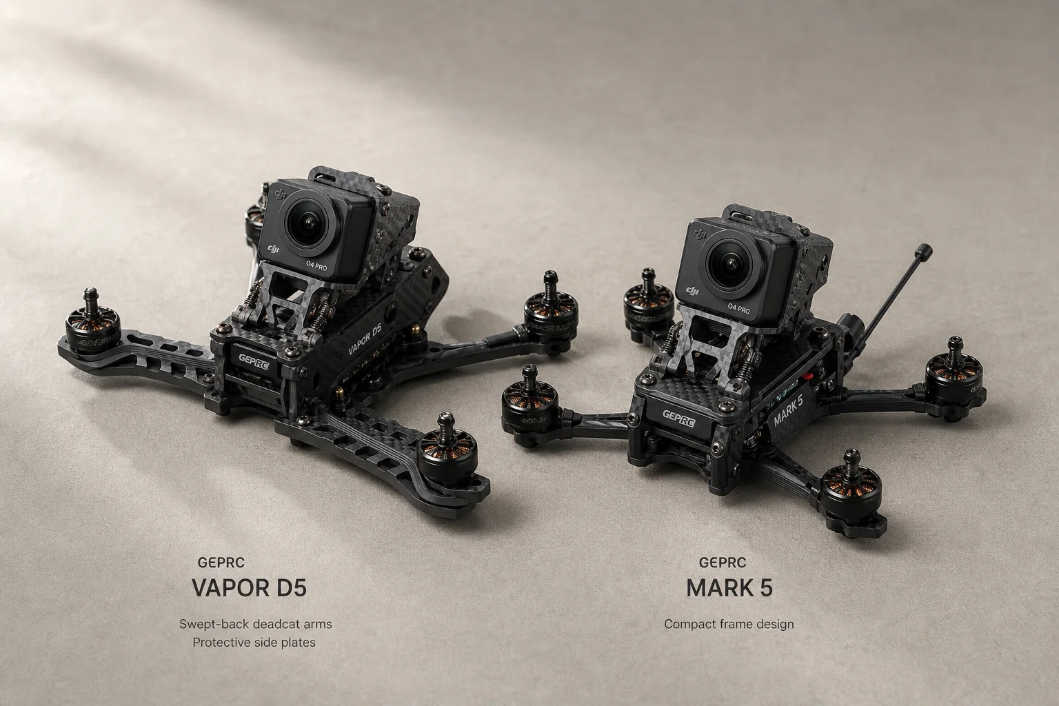
Best 5-Inch FPV Drones 2026: Vapor D5 vs Mark 5 Comparison and Review
A detailed comparison of the GEPRC Vapor D5 and Mark 5 5-inch FPV drones, covering performance, durability, price, and which suits different flying styles.
FPV Drones
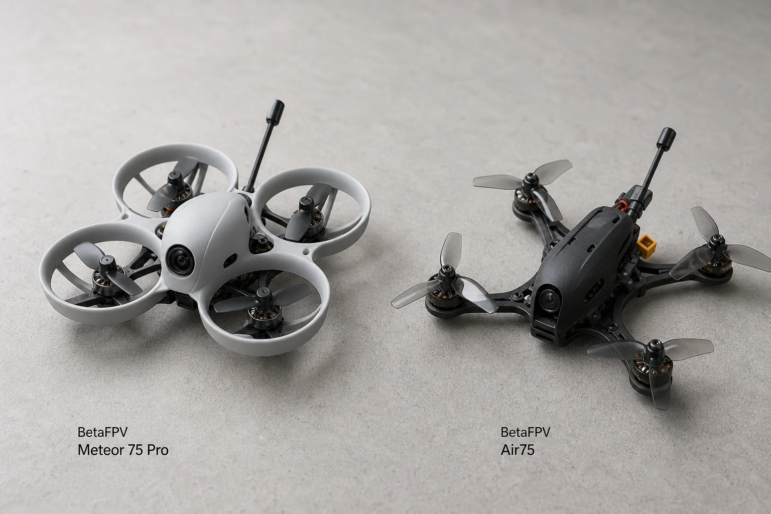
BetaFPV Meteor 75 Pro vs Air75: Which Tiny Whoop Suits Beginners Better
A practical comparison of two popular 75mm FPV drones, tested by a beginner pilot to help you choose between durability and handling.
FPV Drones
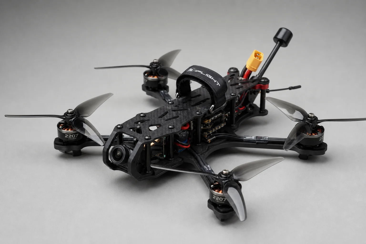
Building a High-Quality FPV Drone Backup: Component Selection and Assembly Guide
A complete walkthrough of selecting premium FPV drone components and assembling a reliable backup quad with the IT'S FPV ERA frame, KISS FC Ultra, and professional-grade electronics.